How to Choose Chip Inductors in SMT Chip Processing?
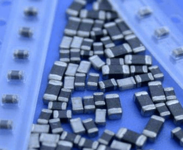
In SMT chip processing, the chip inductors are mainly responsible for turbulence, decoupling, filtering, and tuning. The types of chip inductors are mostly of the winding type and the laminated type. How to select the appropriate chip inductor? How should the performance and appearance quality of SMT components be tested?
Chip Inductors are selected:
1. The net width of the chip inductor is less than the net diameter of the inductor to avoid excessive solder stress causing extreme tensile stress to change the inductance value during cooling.
2. The precision of the chip inductors that can be purchased on the market is mostly ±10%. If the accuracy is higher than ±5%, you need to order in advance.
3. Many chip inductors can be soldered by reflow soldering and wave soldering, but some chip inductors cannot be soldered by wave soldering.
4. When repairing, you cannot exchange the chip inductor with the inductance. It is also essential to know the task frequency band of the chip inductor to ensure the task function.
5. The shape and size of the chip inductor are similar, and there is not any clear mark on the way. When hand soldering or manual patching, do not misplace or take the wrong part.
6. 3 kinds of chip inductors are rare at present: 1. High-frequency inductors for microwaves; suitable for use in frequency bands above 1 GHz. 2, high-frequency chip inductor; suitable for resonant circuit and a frequency selection circuit. 3, general purpose inductance; generally applicable to courses of several tens of megahertz.
7, different products, selected coil diameter is different, the opposite inductance, the DC resistance appearing is not the opposite. In the high-frequency circuit, the DC resistance has a significant influence on the Q value, so pay attention to the design.
8. Allowing large currents to pass is also a goal of the chip inductor. When the circuit demand is subjected to heavy flow, it is necessary to think about this goal of the capacitor.
9. When the power inductor is used in a DC/DC converter, the magnitude of its inductance indirectly affects the task shape of the circuit. In theory, the method of increasing or decreasing the soil can often be used to change the inductance to achieve good results.
10. Commonly used wound inductors for communication equipment in the 150~900MHz frequency band. In frequency circuits above 1 GHz, high-frequency microwave inductors must be utilized.
The above are the top ten considerations when using SMD inductors in SMT chip processing. Better choice of chip inductors to better assure the quality of SMT chip processing.
SMT Appearance Inspection:
The solderability of component lead (electrode terminals) is a significant factor affecting the reliability of SMA soldering. The leading cause of solderability problems is surface oxidation of component lead. Since oxidation is natural to occur, in order to ensure the reliability of welding, on the one hand, measures should be taken to prevent the components from being exposed to the air for a long time before welding, and the wells should be avoided for long-term storage; on the other hand, it is necessary to pay attention to soldering before welding. Sex testing, in order to find problems and process in time, the most original method of solderability testing is visual evaluation, the necessary test procedure is: immerse the sample in the flux, remove and remove excess flux and then immerse in the molten solder bath, When the immersion time is about twice the actual production welding time, it is taken out for visual evaluation. This test is usually carried out using an immersion tester, and the sample dipping depth, speed, and dipping residence time can be precisely controlled as specified.

SMT Component Testing:
Surface-mounting technology is equivalent to place components on the surface of the PCB. For this reason, there are strict requirements on the coplanarity of the parts. Generally, the specification must be within the tolerance zone of 0.1mm. This tolerance zone consists of two planes, one is the pad plane of the PCB, and the other is the plane where the component pins are located. If the three lowest points of all the pins of the component are parallel to the plane of the solder joint of the PCB, and the distance between each pin and the flight does not exceed the tolerance range, the mounting and soldering can be performed reliably. Otherwise, the lead may occur. Welding problems such as foot soldering and lack of soldering.
There are many methods for detecting the coplanarity of component lead. The easiest way is equivalent to place the components on the optical plane and use a microscope to measure the distance between the non-coplanar pins and the visual plane.
At present, the high-precision patch system used generally has a machine vision system, which can automatically detect the coplanarity of the components before the patch, and eliminate the components that do not comply with the requirements.
If you have any questions about PCBA, please feel free to contact us at any time. We have 8 years of experience in electronics and will give you a detailed reply within 5 hours.


