Open circuit or short circuit? How to quickly detect circuit connection failures
How to check the open circuit and short circuit of the circuit connection?
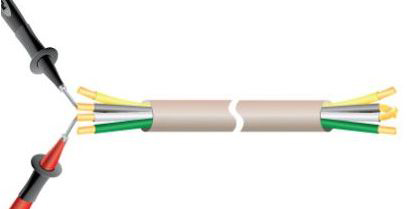
The easiest way is used by a digital multimeter (DMM) for continuity testing. The continuity test is a type of circuit test that can be utilized to verify verify that there are open and short circuits in the circuit connection.

Most digital multimeters have continuity testing capabilities for testing switches, fuses, electrical connection, conductors, and other components. E.g:
1. You can determine if the solder joint is good. If the solder joint is cold soldered, the eye looks like a connection, but it is not.
2. It can be determined whether the wire is disconnected somewhere between the terminals.
3. It can be ensured that the traces on the PCB are not connected to each other because sometimes the solder joints inadvertently connect the two tracks together.
When a digital multimeter detects that a circuit or component is shorted (or intact), most of them emit an audible signal (such as a beep).
Please remember:
①. Be sure to power off the circuit or component that needs to be tested before performing the continuity test.
②. The continuity test is non-directional. This means you can switch probes and get the same results in the test
③. Very low-resistance components (such as below 100 ohms) and general inductors may appear to be short-circuited during testing because they are very close to a single wire connected to a digital multimeter.


